I’m very aware the blog has been quite on progress around the actual layout for the last 18 months or so. The reality is that most of last year and the early part of this year went into building an extension to the house, so the railway got fairly neglected, however since the summer work has slowly moved forward, so hopefully there will be a few more posts on the blog detailing the work.
One of the next areas which has needed attention has been taking the wiring from being just the two main loops to the stage where I can control some of the turn outs and be able to run trains into some of the goods yard sidings.
The concept
When I started building the layout my original thought was that I’d build it all using DCC control since that was the future. That way I’d just run common bus round the board and eventually use the DCC to switch the points also.
The reality has been quite different – I’m still getting up to speed on DCC and how to use it, but more significantly most of my locos are analog control. While the most recent ones have the ability to fit a DCC decoder, and in some cases I’ve bought them ready, a much higher proportion do not or will require significant work to fit.
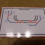
So in the end I reached the conclusion that I needed to add a more classic style control panel to the layout to enable me to switch controllers to areas of tracks, and also switch the points. The key difference here is that as well as being able to switch the analog controllers to the different regions of track I also want to be able to switch parts of all of the layout over to DCC control as and when I’m ready.
So the control panel has three sections – a 4 way Gaugemaster analog controller for basic running, and then on either side switching panels for each end of the layout.
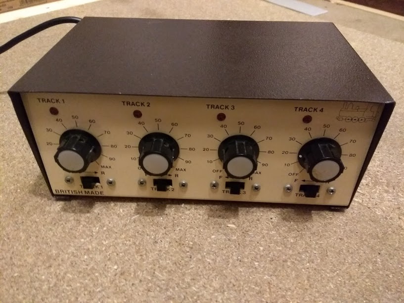
4 channel Gaugemaster controller
This blog post is going to concentrate mainly on the physical construction of the control panel. I’m going to leave the wiring to a future blog post.
Panel construction
How to build the actual control panels themselves was one of the big questions I had when I started this. I did look around and a bit trying to pick up ideas – this post on RMWeb gave me a lot of inspiration, however in the end I’ve done what I think is my own idea.
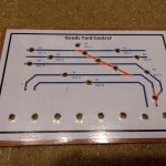
The main design on the control panel was generated in Microsoft Visio. The choice of this was mainly because I have access to it and know it well through work. This allowed me to draw out the basic design, but also to create layers to represent the size and locations of elements such as the switches and structure to make sure they fitted correctly.
Once I’d got the design completed I was able to print it out, cut out and laminate it. This then created a nice clean surface which will hopefully last a long time. Once cut to size the laminated design was then stuck using PVA glue onto a piece of 3mm plywood of the correct size to give strength. I was then able to drill through the laminated paper and plywood to fit the switches needed for the power and point control.
One area I did struggle with was how to deal with the edges and make that look neat. This was not just around the edge of the whole thing, but also between the three sections the overall control panel is made up from. The process of laminating paper made this worse as to make the lamination work well then the paper needs to be cut smaller than the required size to ensure the lamination seals all the way around.
My plan (however I can’t get to this until all the wiring is complete and I’m ready to fasten the panel in place) is to use from right angle plastic that I had kicking around from another project. This is about 12mm right angle, so will overlap the edge of the panel and hide the edge lamination as well as the different layers. Where the different panels fit together I’ll do the same thing, but just with 12mm strips of flat plastic.
-
- Building the basic structure
-
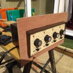
- Testing the controller surround
-
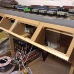
- Structure in place in the railway
-
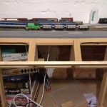
- Another view of the basic structure complete
-
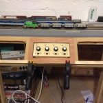
- Testing the controller in the middle slot
Mounting the panel
Once I’d worked out where I wanted them, the actual mounting of the panels was another challenge. I didn’t want them to be flat – either horizontal or vertical – as that didn’t feel very natural to me. Also I have the 4 channel analog controller to mount alongside them, so some careful construction would be needed.
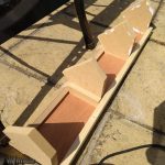
The aim was to have three sections, all angled at 45 degrees from the layout to make operation easy. The outer sections would be the switches, with the middle being the Guagemaster controller. So lots of pieces to fit together accurately but also ensure that things like the controller are well supported and won’t move when operated.
Again, my Visio license came useful here – it allowed me to take designed I’d sketched out and actually plot them accurately to scale. I was then able to print out the 4 key sections that define the size and angle of the controls and use that as a template to cut them out.
From there it became simpler, adding legs, fitting to the layout and adding a bottom piece for the controller to rest on. Some fine tuning around getting the precise positioning for the control panels and analog controller was required during construction, but basically the core design remained unchanged.
-
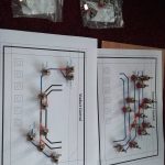
- Testing the switch positions on an initial print out
-
- Finished design laminated and stuck to the wood
-
- Holes drilled ready for the switches
-
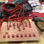
- Part way through adding the cabling
-
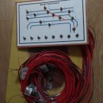
- Cabling finished ready to go up to the layout
-
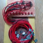
- Underside showing all the cabling
Next steps
The next stage is to actually wire the control panels into place. This work has started for the first panel which controls the goods yard and since much of the required infrastructure (point motors, relay boards etc) was in place then this should be fairly easy. The other end of the layout by the viaduct and stations will take considerably longer as in some places the track is not even laid yet, let alone having all the other bits needed!
As mentioned previously, my aim for a future blog post is to try and explain how the wiring of the layout will work, so I’m going to sign off here in order to have time to actually do the work!