Time for one of those erratic updates with some progress from the model railway!
Over the last couple of months I’ve been doing a lot of wiring to bring all the point motors and additional sections of track that were not working into use. In July’s update I covered the fact that I’d started this work and been wiring up the point motors, however since then I’ve been working on the control panel which allows me to control it all.
It’s almost exactly 3 years go I posted about how I was building the first section of the control panel to be able to control the fiddle yard section of the layout , and since then there have been various posts covering the actual wiring (part 1 and part 2). Using the control panel has been an interesting experience as while it does what it’s supposed to, the limitation in the design to be able to understand which way the points are all set has caused real issues with operating trains. With the second panel needing to control the far side of the layout then this issue is going to be even more obvious so there was a need for a Mark II panel for the next section.
The obvious answer is to add some LED indicators to show which way the points are set at a given point, however while this sounds really simple, in practise this has been a lot more fun than you’d expect!
The first option would be to just use the initial switch on the control panel to indicate which way the points had been requested to go. This has the issues with not necessarily reflecting the actual position of the points – just what was requested – plus needing something to remember which way the points are set as the control is just a brief pulse.
The more conventional way is to use the accessory switch built into the point motors to drive the LEDs. This has the advantage of being built into the motor itself, so should accurately reflect which way it’s switched, so if something fails to happen then the control panel should continue to indicate it. The problem I have with this is that since I am using electro-frog points on the layout to be ready for DCC operation in the future then I am already using the accessory switch to drive the frog polarity (see wiring part 2 for details).
The solution has been to add even more relays to the underside of the layout, so now the accessory switch is used to control two relays. The first of these then takes over the frog switching, while the second then drives the LEDs on the control panel. This adds considerably more complexity to the wiring, but does overcome the issues.
The following diagram shows the whole process of point control from switch on the control panel, through the relay that fires the actual points and then the two sets of relays for the frog and CDU:

With the introduction of LEDs on the control panel I’ve also changed the construction slightly. The previous panel was based around 3mm plywood with a laminated sheet stuck onto it for the actual mimic design. Looking around for LED choices it was a balance between overall size to get as close to the switches as possible and then length of the LED to be visible through the panel. In the end I settled on these from CPC, however the through hole section is only just over 1mm compared to the 3mm plywood. So I’ve changed the base material to be 2mm acrylic sheet which gives the rigidity required, but is slightly thinner which means the LEDs are recessed but not too far.
The following photos show the control panel under contruction:

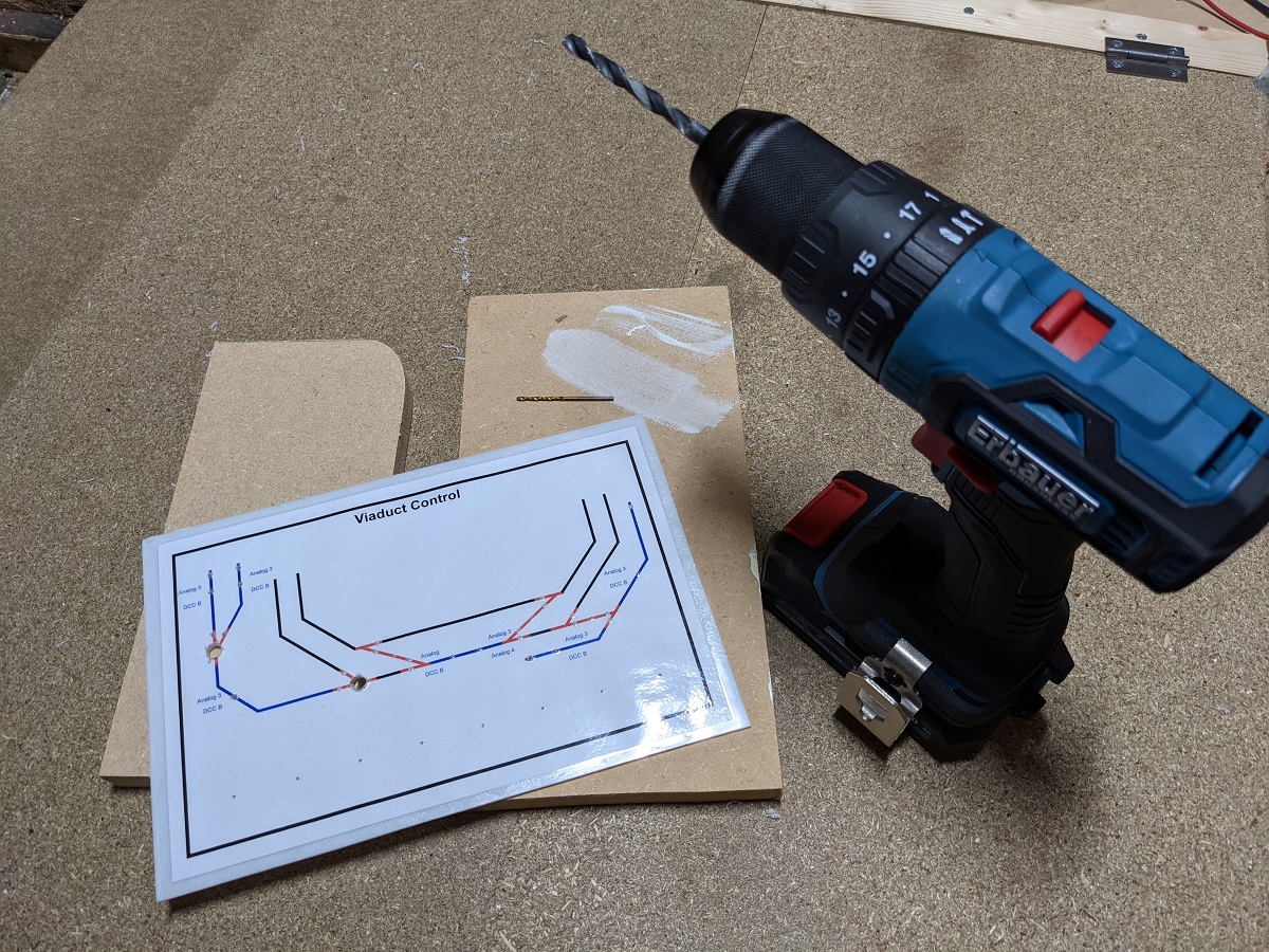
New mimic printed and mounted to 2mm acrylic 
Drilling out the holes for the switched and LEDs 
Top view of the switches and LEDs in place 
Underside showing the switches and LEDs in place 
In the process of adding the wiring 
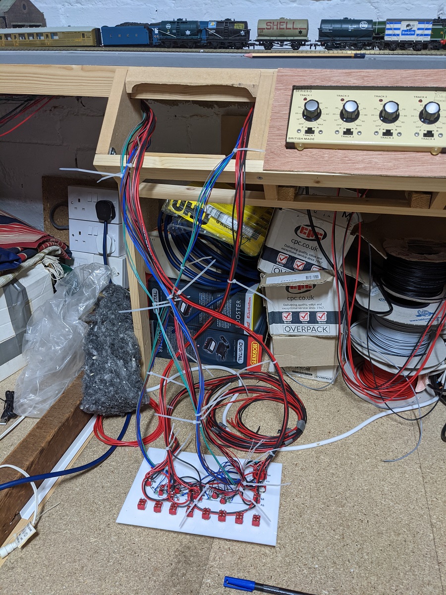
Panel with associated wiring about to be installed to the railway 
Wiring almost ready to go 
Panel in place with route indicator LEDs lit up


Since the control panel now has nice indicators on it of what is happening then the best way to show this in action is through a short video:
So the final challenge now is what to do about the existing control panel. Trying to add LEDs into the existing layout will be a challenge is there is not the space in many of the locations where they are needed. So I’m trying to work out whether I need to follow the model of the second panel and re-design it using the 2mm acrylic and move all the switches slightly to allow for the lights. This will be a significant undertaking as it will probably mean re-doing some of the wiring.
In the mean time I think I will spend some time on some other tasks while the work up the effort to make the changes!