Well, once again it’s been a much longer gap than I intended on updates. Ironically having been through various lockdowns, being stuck at home, not allowed to do a lot of things you’d have thought I’d have managed to make a lot of progress on the railway however this has not been the case. Unfortunately things like work on the house, decorating, children being home-schooled as well as a live streaming for church has managed to fill the time. However the good news is that I have managed to make it back into the loft over the last couple of month and work has slowly started to move forward again.
The focus of the work is really on getting the point motors working on the second half of the layout. About two years ago I got all the point motors at the goods yard end of the layout completed and wired back to the control panel so they all work and can be controlled properly. When work stopped pre-Covid I’d started fitting the motors, but not done any of the cabling. In fact I’d left the layout in a state where the point motors were sticking through the track such that I couldn’t actually run a train all the way around the loop.
The good news is that all the point motors are now in place and have been tested. So the attention has turned to the wiring up of them. I’m following the same basic model described in a previous post here. This involves using a relay board to separate the control panel from the heavy duty wiring that actually powers the point motors. The idea being in time that I could potentially remove the control panel and move to a computer software based model in time and all that would need to change would be the inputs to the relay board, all the rest of the wiring would remain in place.
What I have found in the time since completing the previous control panel is that I am struggling with visibility on which way the points are selected. This has been particularly bad in the goods yard where there are pairs of double slips and at first glance it’s not immediately obvious which way they are set. Additionally at odd moments when the CDU is not fully charged then throwing the points does not always work reliably – I’m relying on the sound to tell me whether it’s worked which is far from ideal.
So I’m not working on a version 2 control panel which will include indicator LEDs so I can see what’s going on. Originally I didn’t include these as they add more complexity to the wiring and as a mentioned previously I was hoping to get to a software based solution at some point. However as has happened a few times along the way, reality and practicality have kicked in and I’m having to change my plans.
I’ll probably do another post in time to go into more detail around the control panel and how this will all fit together as it’s becoming quite complex now as it requires two sets of relays for each set of points!
In the mean time it wouldn’t be a blog post without at least a few photos of the progress and in this case that means lots of photos of wiring underneath the layout!

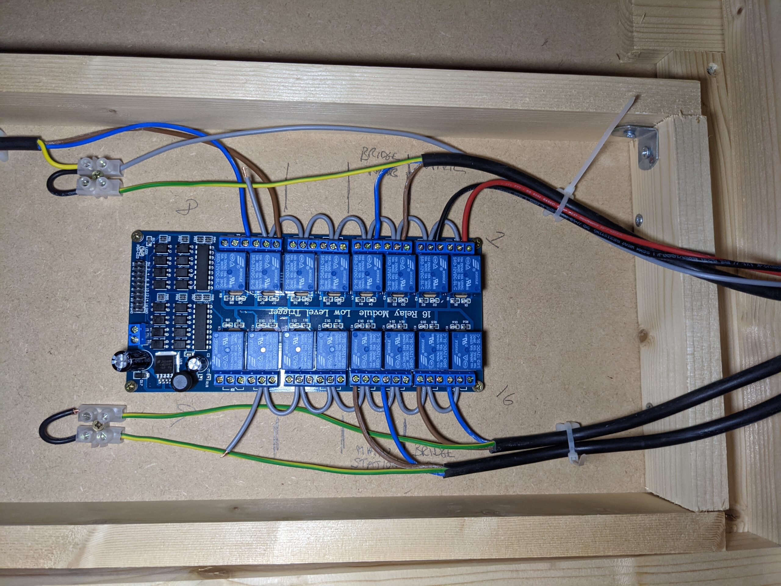
New point control relat board 
Wiring for two point motors and bus power 
Bus power and point motors under the viaduct